|
Seminar History of Computing, SS 2001 Karin Markstad The Harvard Mark I and the ENIAC are both historical computers that have meant a great deal to the developement in the computer field. Here follows a disription of the machines and their inventors. The Harvard Mark I The Harvard Mark I, also known as the IBM Automatic Secuence Controlled Calculator is said to be a monument in the development of the art of computing. Mark I marked the beginning of the era of modern computing and "Babbage's dream come true". 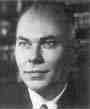 "Don't worry about people stealing your ideas. If your ideas are any good, you'll have to ram them down people's throats." - Howard Aiken The inventor of the Harvard Mark I, Howard Hathaway Aiken was born in 1901 in New Jersey, USA. He was a giant of a man, both in physical appearance and mind. He judged people instantly by simply looking at them. He was an extreme: on a scale from 1 to 10, you would either be a 0 or an 11. His strong will and original mind often caused conflicts thourouhgout his career. He stood six feet tall and was said to have satanistic eyebrows. Aiken was educated in the public school system. All through school and university, he was working full-time in order to support his family. He got a bachelor's degree in electrical engineering from the University of Wisconsin and worked as a successful electrical engineer for ten years before deciding to return to university for further training in science. He enrolled in a physics graduate program in 1931 at Harvard University. Aiken was involved in a small science group, where he was primarily interested in vacuum tubes. For his doctor paper, he reseached conductivity in space charge which involved calculating with differential equations which he simply thought were too time-consuming to calculate by hand, and visioned a machine that could perform all this. He started drawing on a machine and was primarily concerned with the logic and general architecture of the machine rather than technolgy involving choice of components. The components of the machine would depend on the company willing to finance the project. Aiken first turned to Monroe machines and after being turned down, he went to IBM who agreed to build what then was named the IBM ASCC (Automatic Sequence Control Calculator). The machine was hereby built by electromagnetical components rather than using an electrical system. Aiken has said it was only a question of money and which company was willing to pay the bill, but admitted on the same time that in his view, vacuum tubes were unreliable and he preferred slower and more reliable relays. Building Mark I was done between 1939 and 1944 in IBM laboratories by already existing IBM parts as well as special parts constructed for the machine. Conflicts arised between Aiken/Harvard on one side and IBM on the other concering who was really the inventor of Mark I. The reaction from the rest of the world was great when it in 1944 was presented to the public and the the US Navy and during war-time of 1944-45 Mark I ran almost non-stop for the US Navy, dealing with problems associated with magnetic fields: protecting of ships from being destructed by magnetic mines, and radar usage and design. In Aiken's time, the work of Babbage was not greatly known, but Aiken was well aware of and inspired by it. There are many differences between Mark I and Babbage's machines, but the only difference that mattered to Aiken was that his worked. To him, it was Baggage's dream-come-true. Mark I was in terms of architecture, said to lay inbetween Babbage's Difference Engine and the Analythical Engine. Aiken has three different ways to claim fame: - Mark I, Mark II, III, IV, together with methods of numerical analysis - Establishing the pioneering school of advanced computer science - Lectures and articels especially from the computer conferences held in the years after the 2nd World War. Through these, Aiken spread the interest for computer science Aiken was rewarded for his job by many honorary doctorates, medals and memberships in important scientific societies worldwide. Although Mark I meant a great deal for the development in computer science, it's not recognised greatly today. One could ask why; the reason for this is the fact that Mark I (and also Mark II) was not electronic - it was electromagnetical. And why was that? Aiken self explained "I never had any preconceived notion about what kind of components you should use to build a computing machine: mechanical, relays, vacuum, or what. The thing to do was to get the machine built and running so that it would make numbers." Machine description 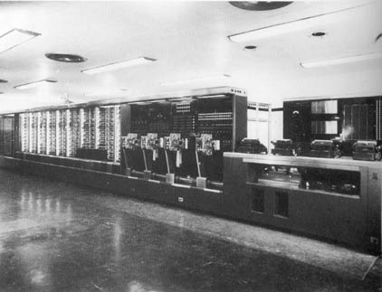  Harvard Mark I Mark I was enourmous in size, measuring 8 feet high, 51 feet long and three feet deep. It weighed 5 tons, used 530 miles of wire and 730,000 separate parts. The operation of these parts was powered and synchronized by a long horizontal rotating shaft. A four horsepower engine drives the mechanical parts. There were 2200 counter wheels and 3300 relay components. Aiken was greatly concerned with the apperance of the machine, and dispite war time and lack of materials, Mark I was covered with steel and glass. Mark I was a very flexible machine, although it was not that automatical as its original name suggests, while much of its operation had to be set manually. Mark I was, in modern terms, a parallel synchronous calculator with a word length of 24; 23 decimal digits and one sign. Calculations are performed decimally with fixed decimal point. The operation unit of the machine consisted of 72 registers called accumulators. Each accumulator held 24 electromagnetical rotary switches, individually connected by a clutch to a drive shaft, by which decimal units, carry, and timing information were stored. This provides for a 23-digit number plus a sign. The accumulators are complete addition and subtraction machines and functions as a storage or memory device. There is no clear separation between storage and arithmetic functions. Some of the accumulators are dedicated to a special function, such as accumulator 70 that deals with the absolute value of a quantity, accumulator 70 that can increase the data amount to be stored (on expense on accurancy), or accumulator 72 that is the automatic check counter.  Accumulators Addition with carry, example: 3279 8935 add 4 adding units digits 1 carry 14 adding tens digits 1 carry 214 adding thousands digits 1 carry 2214 adding ten-thousands digits 1 carry 12214 final answer Mark I clearly favors addition (and subtraction) to the other three fundamental arithmetic operations. There are 72 places where addition could be performed , but only one for multiplication. That depends on the fact how IBM's card reader was constructed, but appearently also because of Aiken simply liked addition. Separate devices took care of multiplication and division. The actual multiplcation involves multiple addition; by withdrawal such many multiples of the multiplicand as it's indicated by the multiplier, and then adding them together. Division on the other hand, are multiple subtractions. There were 60 constant registers that consisted of 10-position rotary switches on which 23-digit signed numbers could be set or retrived through computation. These registers would correspond to what we call programmable ROM, but Mark I's ROM could not in comparison to modern computers, store programs, but simple supplied with numberical constants. Each register contained 24 dial switches which corresponds to 24 digits. Every register had a number used for location of where an instruction should go. As it easily happend that the swithes were falsely set, more prefferable means of input data came through punch cards or Value Tapes. There contents from the input divices were read through four tape readers, whereof one was used for feeding the machine with instructions. The other three held table of functions and could supply values. Internally stored programs performed operations involving sines, logarithms, exponentials and powers. Programs came into the machine through punch cards. Programming was made through first describing the problem in terms of mathematical steps and then consulting the "code book" in order to translate these into machine instructions. The programming part was similar to what we know as programming in machine language. Although Mark I was faster than using other calculation methods of the time, it was very slow in comparison to for example the ENIAC. Here follows a table with time for various operations:
The ENIAC ENIAC stands for Electronic Numerical Integrator and Computer and wab brought out to the public on Febuary 14th 1946 at the Moore School of Electrical Engineering at the University if Pennsylvania. At its 50th anniversary, in 1996, a new, modern ENIAC was constructed, a small 7.4*5.3 square mm thin chip of silicon that performed exactly the same as the 18,000-vacuum-tubes and 30 ton heavy old ENIAC. One wanted to illustrate the dramatic way in what the development has proceeded. The chip was produced using VLSI/CMOS technology. The vacuum tubes used in ENIAC are on the chip replaced with transistors. ENIAC was built between July 1943 and November 1945 and was carried out by the U.S. Ordnance Department of the War Department and costed around $468,000. The goal was to make ENIAC as flexible as possible; serving as a multpurpose machine. That means it could not only perform numerical operations, but also store and retrive results and "perform these operations consecutively or concurrently, with automatic transfer from one step to the next. ENIAC was U-shaped, 2.7 meters high and taking up an area of 10 times 17 meters. It consisted of 40 panels, 3 portable function tables, a card reader and a card punch.The inventors, J. Presper Eckert and John W. Mauchly, were well familiar with desktop calculators. 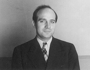  J. Prespert Eckert John W. Mauchly ENIAC was the fastest and largest machine of its time. One great concern was also about constructing it so that the results would bbe highly reliable. ENIAC failed only two or three times a week; a number that pleased even the most skeptics. The faults that were made, was found through special testing functions and it only slowed down the function a few hours per week. When it was presented to the public in 1946, it made great impact in the world of scientific, military and industrial, mostly because its speed. Addition or subtraction of two ten-digit numbers could be done at the rate of 5000 per sedcond. This was 1000 times faster than any other machine of that time with the same accurancy. ENIAC could of course perform addition, subraction, multiplication, division and square-roots, but more importantly, it could storeresults and communicate between units of the machine and even more, execute nested loops and conditional branching. So in many ways, it could appear as the ENIAC is similar to modern computers. However, ENIAC was not able to store programs. Every program had to be set up locally on the various units of the machine by setting switches and connecting units via program trunks (will be explained later). This set-up, that had to be made manually, was naturally extremely time consuming. It was even then considered a down-side, but as ENIAC was inteded to work, it was to perform highly repetitive computations using the same set-up. Machine Description 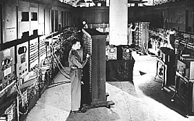 ENIAC One could see the machine as consisting of five parts: arithmetic, global control units, memory, I/O units and busses.  Schematical Functional Diagram Arithmetic units: high-speed multipliplier (dedicated hardware: multiplication function tables) and a combinated divider/square-rooter. Master programmer: used for coordinating the operations of the accumulators and execution of sequenced operations and nested loops. ROM: fast-programmable, provided by three function tables. Constant transmitter: together with a card reader works as the external input device. Global Control Units: include Initiating and Cycling units that master all other operations, initiates computations through providing digits and programs and resets pulses. The ENIAC is an accumulator-based computer, that is the the main arithmetic and data storage units are accumulators. It consists of arithmetic, local control and I/O circuits. The arithmetic unit receives a signed 10-digit number and adds this to a number that already is stored. When a decade counter overflows, a carry-over digit is generated and passed on to the next decade on its left. I also has a binary counter that works as a sign informator. Each accumulator has a control unit that consits of twelve program controls that tell which operation that is to be performed. That is, twelve separate operations cad be performed simultaneously. Eight of these can be set on repeat up to nine times during the course of a program. The program controls are just simple switches set by the user. Each accumulator has a data I/O block which receives or transmits decimal numbers over a bus through five input ports (labeled alpha through epsilon) and two output terminals, an A-port, that transmits the number stored in the accumulator, and an S-port that transmits the 10's complement of the stored number.  Accumulator in the ENIAC Number Representation When constructing the ENIAC, one decieded to use the decimal system and have a maximum width of 20 digits (but number can be twice as large by connecting two accumulators together). The decimal system was chosen because the number of vacuum tubes needed would be considerable smaller. For example, when transmitting a 10-digit number over a decade counter with carry-over capacity, 280 vacuum tubes were needed in the decimal system, in comparison to 450 when using binary numbers.  A programmer changing a vaccuum tube The 10's complement is used for representation of negative numbers. It is obtained by subtracting each number in the digit from 9, and then adding a 1 to the final answer. Also the 9's complement was considered, but it was found that the 10's complement would give higher accuracy when it came to rounding off a number. It is possible to use fewer numbers than 10 when disired by simply setting the least significant number to a 5. Communication The method of transmitting numbers used is serial pulses. It was faster and required fewer vacuum tubes than when using a static system (stead-state signals). Transmitting a number uses a decade counter. A picture is shown below. I will try to make an example in order to explain how the transmission functions. We want to transmit the digit "4". The digit 4 is represented by a 1 in the fifth flip-flop from the left. All other flip-flops are zeros. The values in a flip-flop is shifted one step right for every pulse coming in as an input. During the transmission of a number, 10 consecutive pulses, in the ENIAC called 10P-pulses are used to shift the decade counter one lap around to get back to where it started. This pulse is supplied by the cycling unit. When the 10P-pulse has pushed our 1 to the last stage, at the falling edge, the decade gate is opened, which opens the "Add" gate (normally closed). The "Subtract" gate which is normally open will be transmitting a series of 9P-pulses. But as the Add gate opens, the remainds of the 9P-pulses will instead be transmitted on this gate. That is, in our example, five pulses are transmitted over the Subtract gate and the four remaining pulses of the 9P-pulse over the Add gate. Now the number "4" coming out from the Add outout can be stored, or if disired, the complement throung the Subtract out. However, this was the 9's complement that the receiving accumulator transforms to the 10's complement though adding an 1'P-pulse. It should be marked that the 10P-pulse is ignored on the receiving end.  Pulse transmission in the ENIAC Instructions Some of the operetions performed by the ENIAC, for example addition, is built into the hardware, whereas others require several steps and units. A table of computation and following times is presented below:
Programming The difference between programming the ENIAC in comparison to modern, strore-program computers is great. Programming the ENIAC goes through the following steps: 1) Formulate the problem in terms of mathematical equations. 2) Break the equations down to mathematical operations that the ENIAC is capable to perform. 3) Plan for the storage of numerical data. 4) For each arithmetical operation, set up a program control and make connections between the involved units and I/O. 5) Tie the involved program steps together into a sequential program. An example taken from The ENIAC: History, Operation and Reconstruction in VLSI (Jan Van der Spiegel et al.) follows.  Image illustrationg the steps above Say that we want to have a program that adds two numbers together, using three accumulators. Accumulator 4 stores some numbers, accumulator 5 stores the number b, and accumulator c stores a number c. We want that the program first should calculate (a-b) and store it accumulator 4, then (c+2b+359) and store it accumulator 6, and also increase accumulator 5 by 359. Assume that a,b and c already are present in the accumulators. What will happen? Accumulator 5 needs to transmit the number b to accumulator 4, which is done on Program control 1 (on accumulator 4) by setting the Operation switch to alpha (input port alpha on accumulator 4 will receive the digit). A cable connects the alpha port to a digit trunk, let us call it trunk I. Accumulator 5 must transmit the digit in two ways: once "normal" as it is stored and once as its complement. This is done by using a Repeat program control, which is set to 2. The Operation switch needs to be set to AS so that numbers of both signs can be transmitted. The "S"-output (subraction) on accumulator 5 must be connected to the digit trunk I. Next, the accumulator 6 must receive the number b (from accumulator 5) twice, which is done by setting the Repeat switch of program control 5 on accumulator 6 to 2. An input port on accumulator 6 needs to be connected to the "A"-output (addition) through a digit trunk II. The number 359 (or of course any other number) will come from a card reader to accumulator 5 and 6 through the Constant Transmitter. On accumulator 5, we use program control 6 and on accumulator 6 program control 1. The Constant Transmitter's output needs to be connected to the input terminals alpha and beta on accumulator 5 and 6 respectively over digit trunk III. Then we must set up so that the sequence can be initialized, that is, we must connect input and output terminals in a proper way. The start pulse from the initializing unit's output through a Program trunk A, is (through a line A-1) connected to the input terminal of program control 1 of accumulator 4, and to the program input terminal 5 of accumulator 5 and 6. When accumulator 5 has transmitted its number twice, it will generate an output pulse on on program control 5, which needs to be connected to the program input terminals of control 1 of accumulator 6 and to control 6 of accumulator 5 (that is, where the number 359 comes in), as well as to the program input terminal of the Constant Transmitter. After receiving the initializing pulse, the three accumulators start to work in parallel. After one addition cycle, accumulator 4 will store the number (a-b) and then stop, while the other accumulators will continue to transmit and receive digits. After the next cycle, accumulator 6 stores the number (c+2 b) and accumulator 5 generates the pulse that initializes the transmission from the Constant Transmitter to accumulator 5 and 6. Then the output terminal of program control 6 of accumulator 5 will generate a program pulse that can be used to initialize more operations of the ENIAC, or the machine will stop. Units of the ENIAC - Control Units There are two types of control units, initiating unit and and cycling unit. The task of the initiating unit is to turn the power on and off and to initiate computation and clearing. The cycling unit provides the basic signals to the other units which makes them to transmit numbers. The cycling unit provides for the user to choose between to dubugging modes: "Addition Mode" or "Pulse Mode". The difference between the two is that when Addition Mode is chosen, ENIAC goes through a whole addition cycle and with Pulse Mode, the machine produces one pulse at a time. The cycling unit can generate 10 different types of pulse trains that govern the transmission and generation of numbers, program control, number correction and decade flip-flop reset. These pulses can be combined in order to form any number between 0 and 9. - Accumulator An accumulator in the ENIAC works as an ALU plus a register in a modern microprocessor. The accumulator can be divided into the arithmetic/storage unit and the program control unit. The arithmetic unit consits of ten wood-like slabs. Each slab's function is to represent a digit, which is indicated by the position of the neon bulb in one of the ten stages connected serially. The decade counter on an accumulator is a walking-one ring-counter. The decade counter receives its input from one of five input channels (alpha through epsilon) and the numbers are transmitted through two output channels: A (Add) and S (Subtract). What the accumulator performs is depending on program settings. On the Program Control Unit, there are Operation switches which determine which one of the five operations one wants the accumulator to perform. The five tasks are transmit additively (A), transmit subtractively (S), transmit both A and S (AS), receive on one of the five ports, or do nothing (O). There are twelve Operation switches and each one is linked to a program input terminal. Eight of these twelve can be set in Repeat mode, which performs the task repeatedly up to nine times. A clear-correct switch makes up for the dropped unit pulse in the complement when performin operations that involve shifting (multiplication, division, square-rooting). On the accumulator there is a switch which can be set to the disired number of digits in use for an operation. Condition branching (if... then... else) is taken care of the accumulator as follows. Let us assume that if xis less than b, then one program should be run, otherwise another program. This is done by checking the sign of x-b. Through a sign lead (PM), the output from A and S can stimulate the different programs. - Master Programmer The task of the Master Programmer is to coordinate between the operations of 20 accumulators and to simplify looping. The Master Programmer consists of two panels that have 10 pulse-counting channels, five on each panel. A unit of the Master Programmer has ten decade counters and five 6-stage stepper counters. The stepper counter is set to how many times one wish to perform for example an addition before going on to the next stage and uses the decade counters. - High Speed multiplier Because of multiplication is a usual operation, there is a special hardware taking care of the operation. It is used to multiply two signed, ten-digit numbers. In its operation, it normally uses four accumulators. Two of tese are used for storing the multiplier (`Ier) and the multiplicand (`Icand). The multiplicand is multiplied by consecutives of the multiplier and partial products are thereby produced. Multiplication of a ten-digit number with a p-digit number takes (p+4) addition times. The high-speed multiplier consists of large tables that map digits of the `Ier to digits of the `Icand. The multiplier has 24 Program Controls which makes it possible to perform 24 different types of multiplications during one program. Each program control consists of a tranceiver with in- and output terminals for program pulses. - Divider/Square-rooter This unit controls accumulators to perform the actual operations involved. It uses four accumulators, one for the numerator, one for the denominator, one for the quotient and one for shifting. The operation involvs set-up, calculation, round-off and interlock and clearing. Division is made based on a division algorithm which involves repeated additions and subtractions. When the numerator and denominator have the same sign, the latter is subtracted for the other until a sign change takes place. Is the sign different is it instead added. Every subtraction causes an increment in a decade of the quotient accumulator. The place in which the sign change takes place is moved one step further right for every sign change. For example, if the two numbers are both positive, the quotient accumulator holds the number of times that the content of the denominator accumulator can be subtracted from the numerator accumulator in order to cause a sign change, plus one. Then this digit must be shifted left one step, and the next digit in the result can be calculated in the same way keeping track of the decade. This can be repeated as long as desired. The square-root calculation is based on the fact that the square of an interger a is the sum of the first a odd integers. As in division, square-rooting involves subtacting and addition, sign changes and shifting. - Programmable ROM The function tables can be viewed as what in modern computers are programmable ROM. Memory was very expensive and consisted in the ENIAC of internal and external storage. The internal memory consists of the decade counters in the accumulators and of three function tables. External memory is punch cards used together with the constant transmitter. The function tables are used when solving differece equations, which involves multiplying coefficients to variable values. These constants are looked up by the function tables. The function table works as an array of signed 10-digit numbers of length 104. The values of the numbers can be set on a panel of switches. There are many settable switches and terminals on the units of the function table where the operations are mastered and for argument input and function output. - Input/Output devices The external devices of the ENIAC are the IBM card reader and the Constant Transmitter. Just as external devices are today, the constant transmitter is a mix of electronic and mechanichal components. The IBM card reader reads values used to set switches from punch cards and supplices this information to the constant transmitter. An punch card can store 80 digits and is read by the speed 120 to 160 per minutes. This value is slower than the speed of which the ENIAC performs calculations, but as the ENIAC is constructed to solve problems involving many iteration, it is not a major problem. The constant transmitter has switches associated with tranceivers with input and output ports communicating with the rest of the units if the ENIAC. The card reader can either be activated by a pulse from the Initiation Unit, or mechanically by pressing a button. Neon tubes on the ENIAC display the numbers stored in each accumulator which makes it possible for an observer to follow an operation taking place within the machine as he or she sees the digits "rushing by". This is a great help in order to identifying unit of the ENIAC is not working correctly when the machine is set in a debugging mode. Hopefully, from this essay it's understood the function and importance of these two historical computers and their inventors. For further reading, please consult the below sources. Literature: Jan Van der Spiegel et al, The ENIAC: History, Operation and Reconstruction in VLSI The Harvard University Computation Laboratory, A Manual of Operation for the Automatic Sequence Controlled Calculator I. Bernard Cohen, Howard Aiken and the Dawn of the Computer Age |